Blueprinting
A blueprint is a way to display a drawing documenting architecture or an engineering design details using a contact print process and several layers of thin sheets. Introduced in the 19th century, the process allowed rapid and accurate reproduction of documents used in construction and industry to cut down on time-consuming hand copies and the possibility of copy errors in the era before inexpensive photocopies. The blue-print process was characterized by light colored lines on a blue background, a negative of the original formed by thin layers of an ammonia, potassium, iron, and cyanide solution on the underlayers of paper.
Even though most architectural and engineering diagrams are now executed using computer-aided design or digital pen interface and printed on white paper, the diagram of the original design is often referred to as a blueprint; commissioned work for important clients or for public display are often still rendered with white lines on a blue background to give viewers a feeling of the special nature of the diagram.
Even though most architectural and engineering diagrams are now executed using computer-aided design or digital pen interface and printed on white paper, the diagram of the original design is often referred to as a blueprint; commissioned work for important clients or for public display are often still rendered with white lines on a blue background to give viewers a feeling of the special nature of the diagram.

Blueprinting: Types of Diagrams
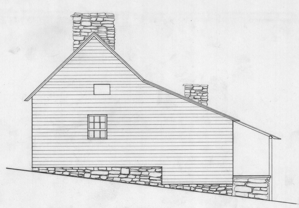
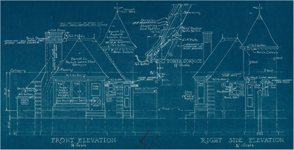
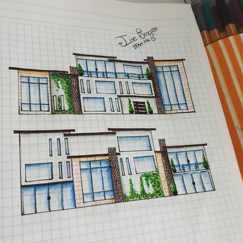
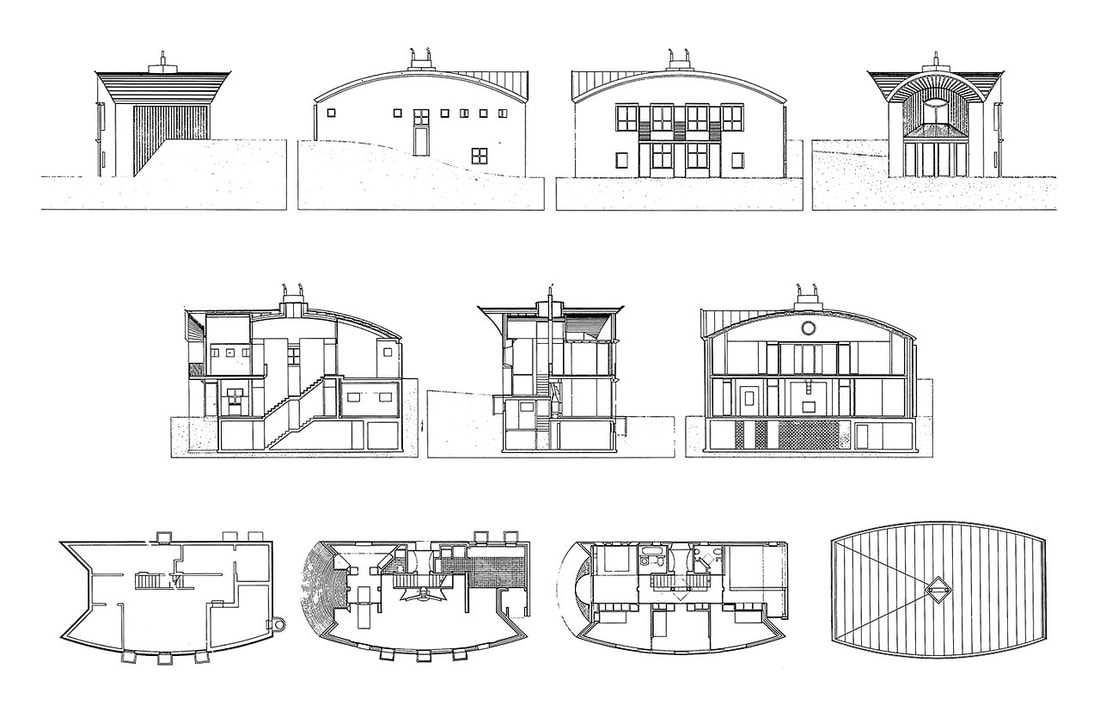
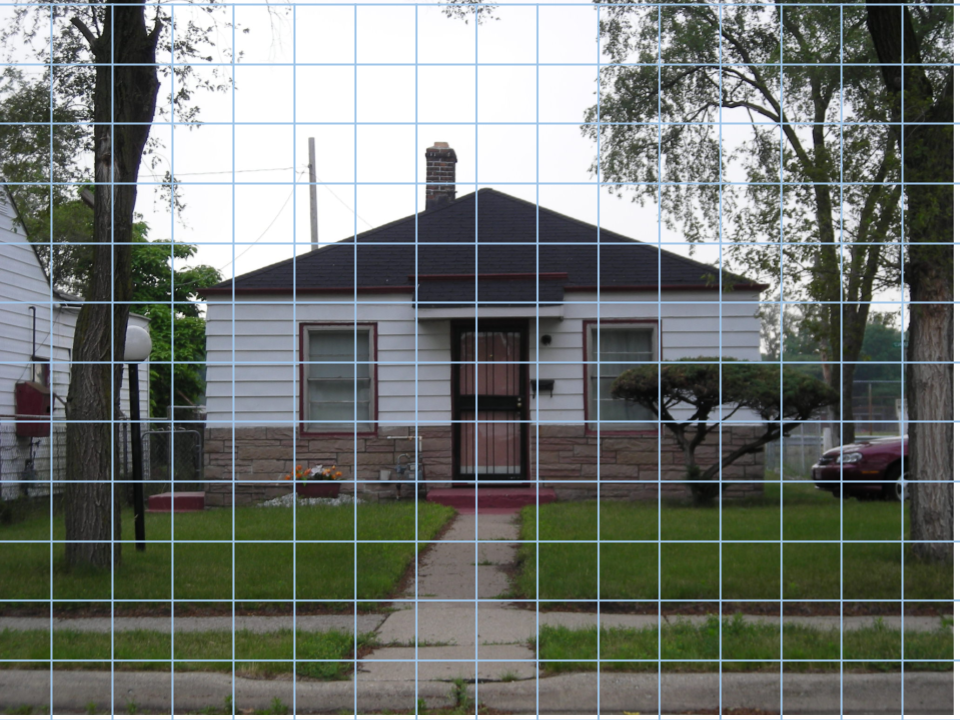
Elevations An elevation allows designers and clients to visualize the street-level view of the front, side, and rear facades of the structure. This is usually the first diagram created, and will usually be a collection of several possible options that the designer and client will narrow down to a final selection of the best ideas.
|
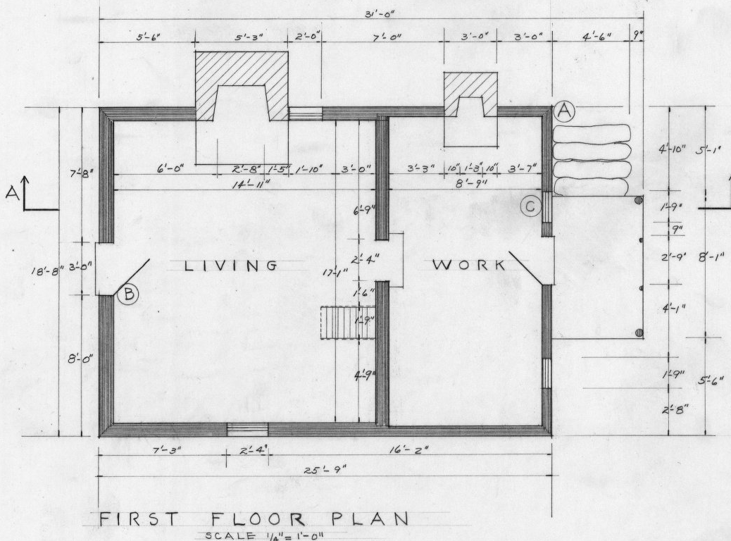
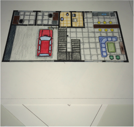
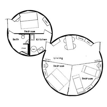
Floor Plans A floor plan allows designers and clients to visualize a top-down or bird's eye view of the interior of the structure. This is usually the second diagram created, and will help ensure each room's purpose will be matched by appropriate placement of windows, doors, electricity, heating and air conditioning, and plumbing details. Again, several possible options that the designer and client consider over time will end with a final draft used by the construction crew.
|
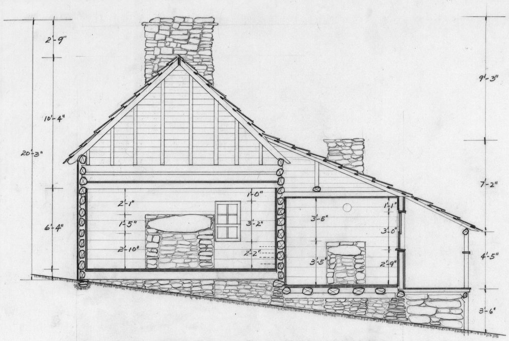
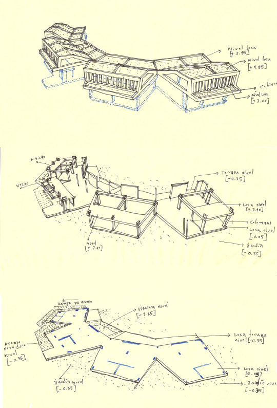
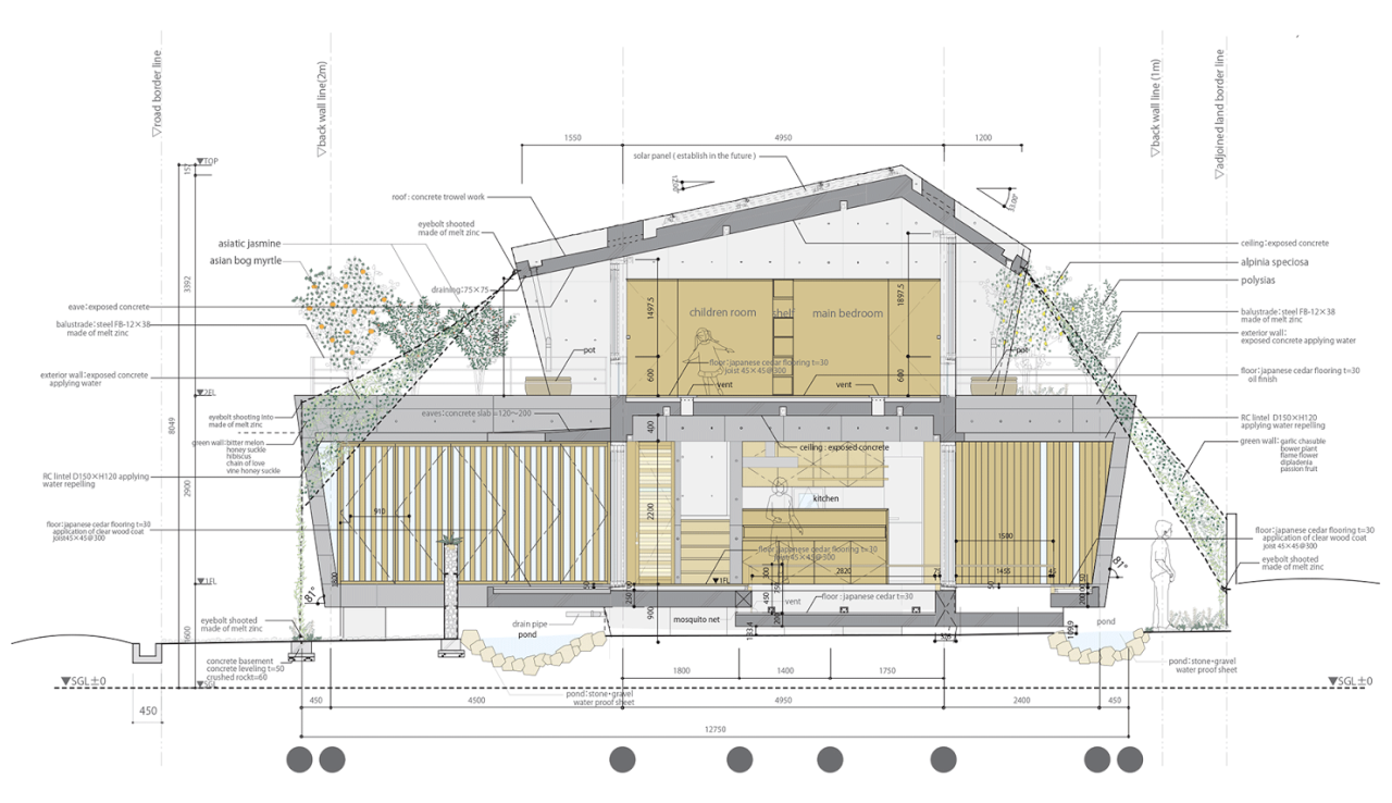
Cross Sections A cross section allows designers and clients to visualize how the different rooms on different levels of the structure will interact with or impact one another. For example, you may not want the music practice room below the basketball court. It also helps the designer and client to consider the movement of people from one space to another, the flow of traffic between spaces. This is usually the final diagram created, but the new ideas it creates will often cause significant changes to the floor plans or even the elevation.
|
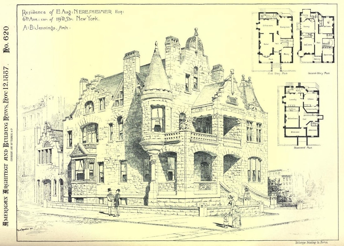
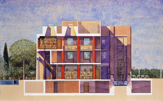
Residence of E. Aug. Neresheimer, New York
|
|
Designs by Architects Christoph Zürcher and Christian Eichler, Bamberg, Germany
|
|
Villa Andrea, architect home and office in Barcelona, Spain. Oscar Tusquets Blanca, 1989-91.
|

|
Getting Started
- Gather your research notes, sketches, images, and dimensions of the structure you plan to build and ensure they are safely stored in your portfolio at day's end.
- Use graph paper (1/4 inch) for your design, estimating the height and width of paper needed based on your dimensions calculations. Think ahead to use the paper in portrait (tall) or landscape (wide) orientation to avoid waste.
- Tape sheets of 1/4" graph paper together with transparent tape, taking care to overlap the paper slightly and match the gridlines.
- Create a point of origin at the lower left corner of the graph paper where the first row and first column intersect.
- Count one inch to the right and one inch up and mark the intersection. This will be the lower left corner of the front elevation, or facade, of your building design. This will leave space for symbols, notes, and possible drafting or cutting mistakes along the edges and bottom of the graph paper.
Drafting Your Design
- Always use a straight edge, triangle, curve guide, protractor, or plastic/metal template on blueprints; no freehanding!
- Begin by drawing the front elevation, followed by the right side (oriented from the front view of the building), rear, and left side.
- Only include the exterior walls of your design; roofs will be constructed of different materials, and any internal details will use recyclables rather than foam due to the expense.
- Mark doors and windows to be cut out with solid lines and well-defined corners or curves. Please do not expect the teacher or adult volunteers to cut muntins, panes, or details on pediments or columns; these will be smaller details you will add in the final stages.
- Mark connecting edges between front and side faces (and side and rear faces) with dotted lines; these will be scored with a knife, but not cut through. This will allow the foam to bend into the corner without needing adhesives (tape and glue).
- If you continue your design on a new sheet or another part of the same graph paper, compare the edges where the sides will meet to ensure they are the same height; line up 2-story walls that meet and 1-story walls that meet at an edge.
- Compare frequently! The front and rear elevations will usually be the same width; the left and right elevations will usually be the same width.
- Take care that the height of windows and doors on different sides of the house are true to your design--usually window sills will be at the same height and doors will be the same height and width.
- If you are using symmetry as an element of design, take time to identify and mark the center of your facade/front elevation; measure windows and doors from this point to ensure a pleasing symmetrical effect.
- Take care that any gables are the same height and angle for the two opposing sides of the house where they appear; if the roof line is not symmetrical as a deliberate design decision, the two sides should be reflections (mirror images) of each other when stacked together.
- Compare all places where the elevations meet to ensure the scale and measurement are correct.
Graph Paper and
Google Drawing Table Grids

|

|
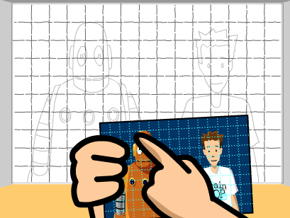
It may be helpful to have your reference photo of your front elevation in a Google Drawing; you will always have access to it from home or school rather than keeping track of your paper copy. You can also re-scale the grid (so long as you make sure it is still a square grid system).
- Find a photo: here is a good starting point, or perhaps here
- Select an image and save it to your drive, Google Drive, or copy it to the clipboard using your mouse, menu, or keyboard shortcuts
- Set the photo of your chosen structure in a new Google Drawing canvas
- Two-finger (or right) click and Order, "Send to back"
- Select Table, then set the width and depth. We suggest you use the 16 (wide) x 12 (high) grid system because this will result in a model that is of a size you can easily find space for it in your home at the end of the project
- If the table is behind your photo, two finger (or right) click, Order, "Bring to front"
- If the table becomes stretched so it has rectangles rather than squares, select Table, then Distribute rows or Distribute columns to sort it out
- You can set the table border color and thickness to a level that suits you--you want high contrast to see the grid and photo details easily and be able to keep track of rows and columns as you draw your diagram
- You can move the table so a reference grid line lines up exactly with your roof line or the edge of the house; once you start your blueprint, however, you need to leave it in place so your scale and perspective stay the same
- Don't panic; the Undo arrow is your unfailing friend if, for example, your photo ends up the size of a postage stamp inside your table
- Of course, you can always use one of the files below as a quick-start kit; do please change the photo, however
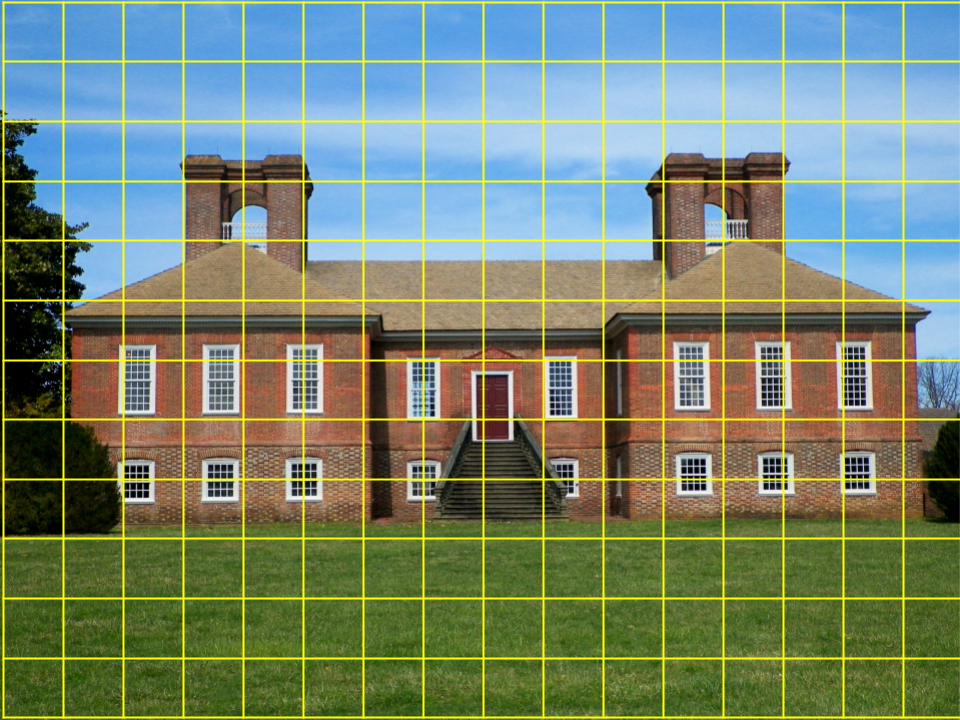
Sample Google Drawing: Joseph R., Georgian Mansion, Stratford Hall, Virginia
You may access it via Google Drive and make a copy
Google Drawing: Josie W., American Ranch Style (Michael Jackson Childhood Home), Gary, Indiana
Buckminster Fuller twin dome house design.
|
Japanese contemporary design, Okinawa, Japan.
|
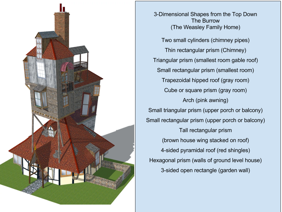
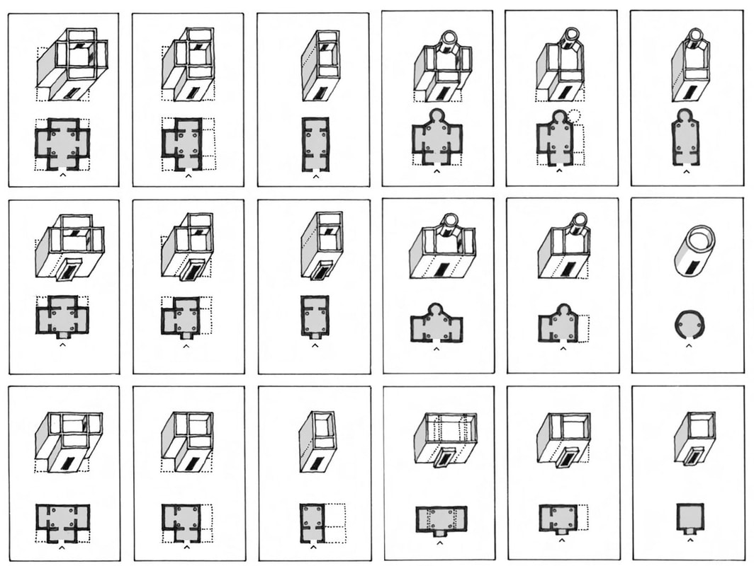
The Naming of Shapes
One-of-a-Kind Structures and Difficult Photography Angles
There are times when you would like to create a structure from your imagination, or from a description in a book, or an existing building based upon a photo that is the best you can find but taken at an odd angle. Graph paper may not be the best tool; it may be time for an organized, thoughtful listing of the shapes you observe in the structure, from the bottom-up or the top-down.
All shapes in human design or in nature can be composed of simpler shapes that can be described.
The listing helps focus your mind on the prisms that need to be cut to assemble the model. Using descriptive language (larger than, smaller than, largest, smallest, height, width, length) will help in scaling the model.
Once you know how many parts are needed and the amount of foam board they will each require, you can begin by drawing a net (a two-dimensional plan for a three-dimensional shape) for the largest element. The next prism will be smaller than the first but scaled to the proportions of your image or vision.
While the naming of shapes can be completed in a sketchbook, journal, or by using a printed out photo, Google Drawing includes several tools that can be helpful. Two files below suggest some options, and can be saved as copies in your own Google Drive as a pattern for your own designs.
Gabby C.--The Burrow--Naming the Shapes
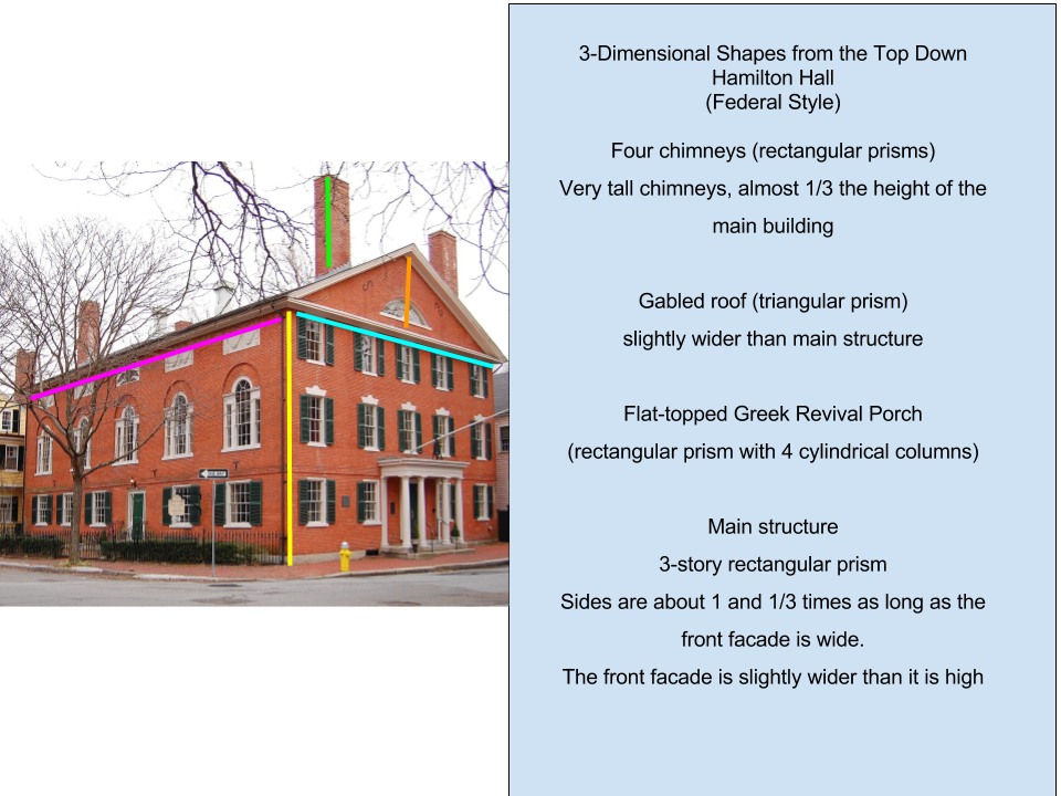
Cora T.--Hamilton Hall--Naming the Shapes
Wolf Schijns, Vernacular Architecture of the Dogon
Precision and Scale are Important!
|
"Stonehenge" from This is Spinal Tap, Rob Reiner, 1984
|
Transferring to Foamboard
- Once your design has been approved by the Architectural Board, select foam board of the right size for your design; work at the edges of large pieces to enable other students to use the remainder of larger pieces of foam board.
- Secure the corners of your blueprint to the foam board using masking tape (the adhesive on masking tape will peel off cleanly from the foam board when the project is complete; the adhesive on transparent tape will tear the outer paper layer on the foam board).
- Using a straight edge, retrace the outline of the front elevation and key elements (doors, windows, gables) to be cut from the foam board; mark the edges where the facade and right elevation, right and rear, and rear and left elevations will meet with dashed lines so the teacher or adult volunteers know where to cut and where to score (scratch) the foam board.
